Construction of Current Transformer:
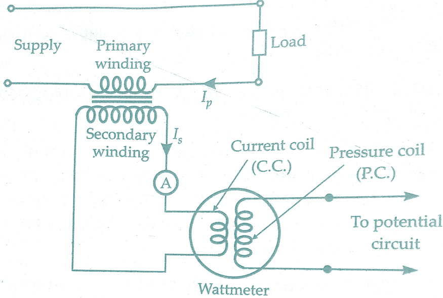
The current transformer is used with its primary winding connected in series with line carrying the current to be measured and, therefore, the primary current is dependant upon the load connected to the system and is not determined by the load (burden) connected on the secondary winding of the current transformer.
The primary winding consists of very few turns and, therefore, there is no appreciable voltage drop across it. The secondary winding of the current transformer has a larger number of turns, the exact number being determined by the turns ratio. The ammeter, or wattmeter current coil, are connected directly across the secondary winding terminals.
Thus a current transformer operates its secondary winding nearly under short circuit conditions. One of the terminals of the secondary winding is earthed so as to protect equipment and personnel in the vicinity in the event of an insulation breakdown in the current transformer. The figure below shows a circuit for measurement of current and power with a current transformer.
Must Read:
Types of Current Transformers:
The following are different types of current transformers :
(i) Wound type current transformer:
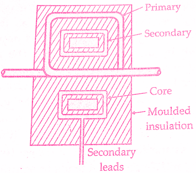
A current transformer having a primary winding of more than one full turn wound on core. The figure below shows the wound type transformer.
(ii) Bar type current transformer:
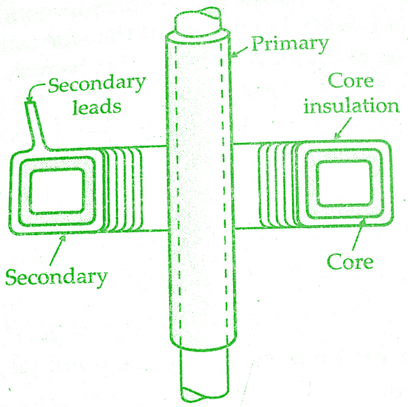
A current transformer in which the primary winding consists of a bar of suitable size and the material forming an integral part of the transformer.The figure below shows bar type transformer.
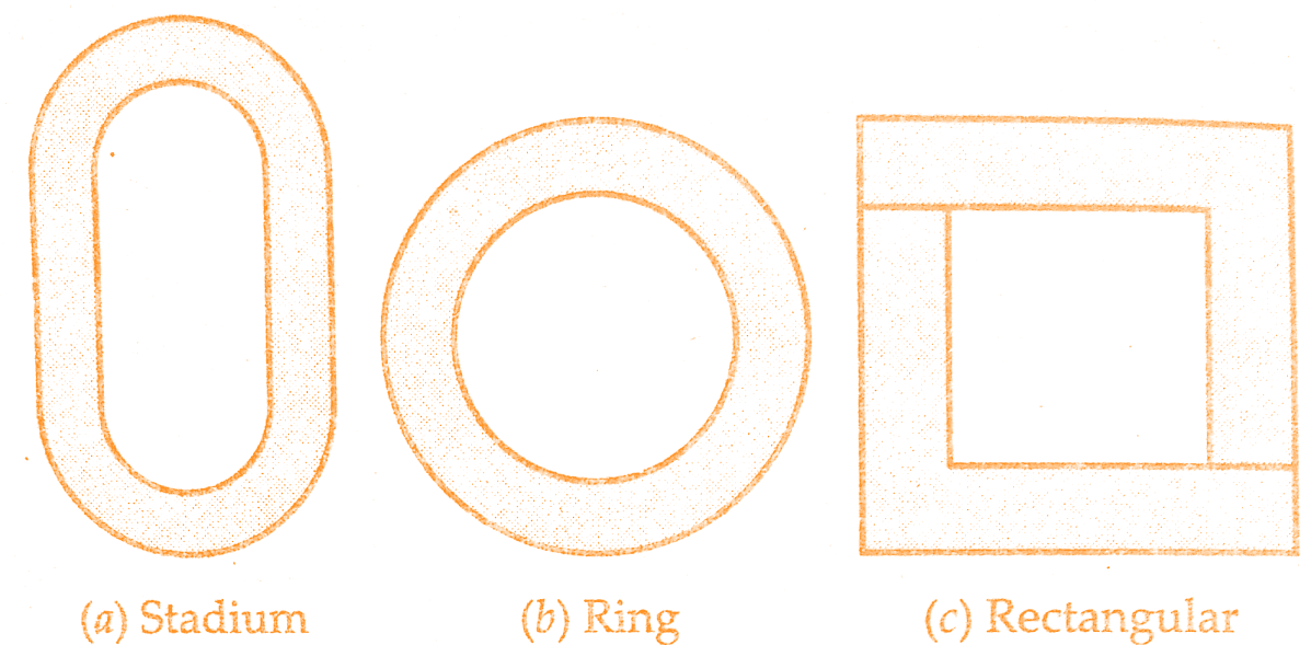
The simplest form any current transformer can take is the ring type or Window type, examples of which are given in the below figure which shows three commonly used shapes i.e., stadium, circular and rectangular orifices. The core, if of a nickel-iron alloy or an oriented electrical steel is almost certainly of the continuously wound type.
But current transformers using hot rolled steel will consist of stack of ring stampings.Before putting secondary winding on the core, the latter is insulated by means of end collars and circumferential wraps of elephantide or presspahn.
Must Read:
These pressboards, in addition to acting as an insulating medium, must also protect the secondary winding conductor from mechanical damage due to sharp comers.The secondary winding conductor is put on the core by a toroidal winding machine although hand winding is still frequently adopted if the number of secondary winding turns is small.
After the secondary winding has been placed on the core, the ring type transformer is completed by exterior taping with or without first applying exterior end collars and circumferential insulating wraps.
A near relative of the ring type current transformer is the so called “bushing type” transformer.This is, in fact, indistinguishable from of the ordinary ring type but the term is used when the current transformer fits over a fully insulated primary winding conductor such as over the oil end of a terminal bushing of a power transformer or an oil circuit breaker.
At very high voltages, the insulation of the current carrying conductor from the measuring circuit becomes an expensive problem. At 750 kV, cascaded current transformers are used or alternatively a coaxial shunt is used to modulate a radio frequency signal that is transmitted from the shunt placed in the high voltage line to receiving equipment on the ground, thereby overcoming the insulation problem.However. this type of system has severe limitation in its power output which has to be amplified in order to operate relays etc.
Must Read:
In a split core current transformer, the core is split, each half having two finely ground or lapped gap faces.These current transformers are assembled onto the primary conductor “on site” for either permanent or temporary duty.
In a bar type current transformer, the core and secondary windings are the same as in a ring type transformer but the fully insulated bar conductor constituting the single turn primary winding is now an integral part of the current transformer.The insulation on the primary winding conductor may be bakelized paper tube or a resin directly moulded on the bar.
In a low voltage wound type current transformer the secondary winding is wound on a bakelite former or bobbin and the heavy primary conductor is either wound directly on top of secondary winding, suitable insulation being first applied over the secondary winding or the primary is wound entirely separately, taped with suitable insulating material and then assembled with the secondary winding on the core.
In the manufacture of current transformers assembly of lamination stacks demands somewhat greater core cross-section than ordinary transformers in order to keep down the reluctance of the interleaved corners as low as possible so as to minimize the magnetizing current.Sometimes cut cores are used.
Must Read:
Whenever possible secondary windings should utilize the whole available winding length on the core, the secondary winding turns being suitably spaced to accomplish this and the insulation between secondary winding and core bed earth must be capable of withstanding the high peak voltages caused if the secondary winding is open-circuited when primary winding current is flowing.
In the case of a large number of secondary winding turns, requiring more than one winding layer, the frequently adopted technique is to sectionalize the secondary winding so as to considerably reduce the peak voltage between layers.
With wound primary current transformers this particular problem is rarely met but it is of importance to try to obtain good relative positioning of primary and secondary winding coils, thus minimizing the axial forces on both coils caused by primary winding short circuit currents.
The windings should be close together to reduce the secondary winding leakage reactance as the leakage reactance increases the ratio error. Round copper wire of about 3 mm² area is frequently used for secondary windings rated at 5 A.Copper strip is used for primary winding, the dimensions of which depend upon the primary winding current.
Must Read:
When using bar type primary, the external diameter of the tube must be large enough to keep the voltage gradient, in the dielectric at its surface, to an acceptable value in order to avoid corona effect.
The windings must be designed to withstand, without damage, the large short circuit forces that are caused when a short circuit takes place on the system in which the current transformer is connected.
The windings are separately wound and are insulated by tape and varnish for small line voltages.For voltages above 7KV, the transformers are oil immersed or compound filled.
Conclusion:
Now here we have learnt Current Transformer – Working, Types & Construction.You can download this article as pdf, ppt.
Comment below for any Queries.


