Transfer Function of Armature Controlled DC Motor:
The speed of DC motor is directly proportional to armature voltage and inversely proportional to flux in field winding. In armature controlled DC motor the desired speed is obtained by varying the armature voltage. This speed control system is an electro-mechanical control system. We will discuss transfer function of armature controlled dc motor.
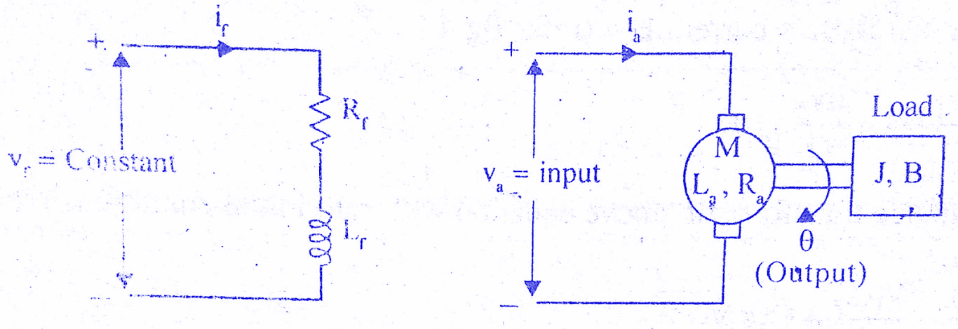
The electrical system consists of the armature and the field circuit but for analysis purpose, only the armature circuit is considered because the field is excited by a constant voltage.
The mechanical system consist of the rotating part of the motor and load connected to the shaft of the motor. The armature controlled DC motor speed control system is shown in the below figure.
Let Ra = Armature resistance,
La = Armature inductance
Ia = Armature current
Va = Armature voltage
eb = Back emf
Kt = Torque constant
T = Torque developed by motor
θ = Angular displacement of shaft
J = Moment of inertia of motor and load
B = Frictional coefficient of motor and load
Kb= Back emf constant
Must Read:
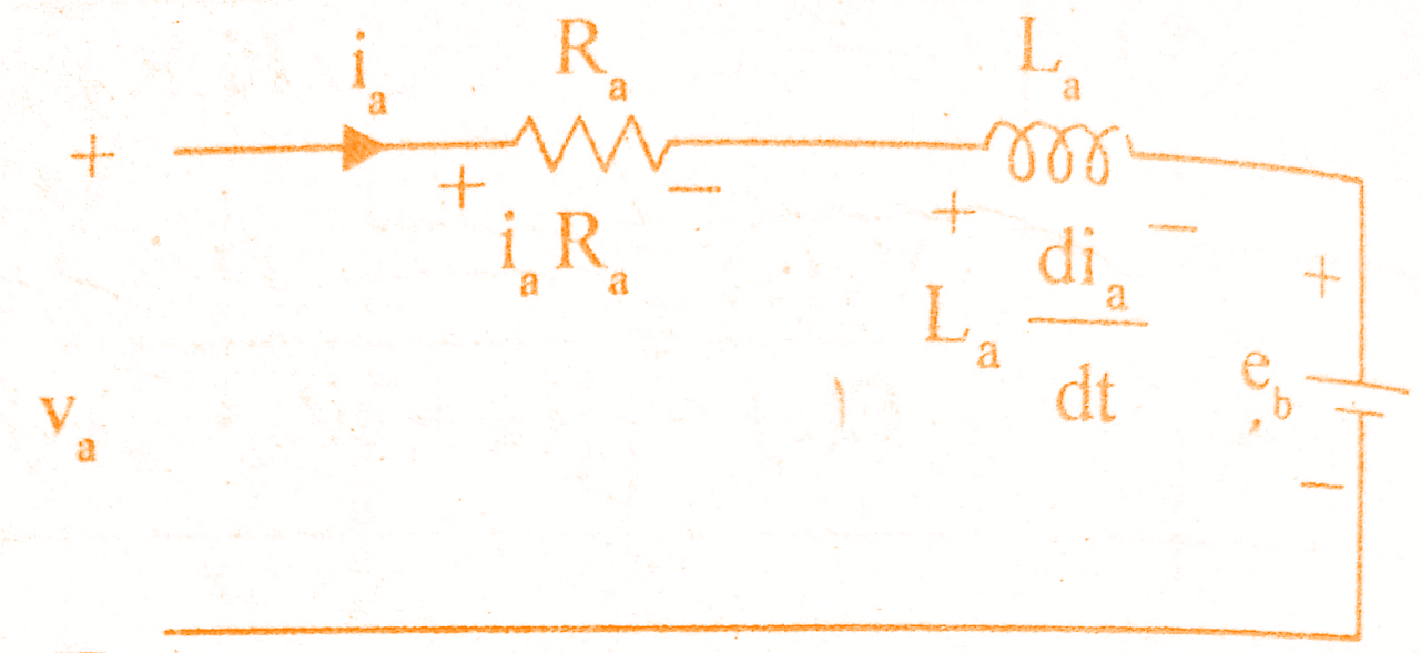
The equivalent circuit of armature is shown in the below figure.
By Kirchoff’s voltage law, we can write,
Torque of DC motor is proportional to the product of flux and current. Since flux is constant in this system, the torque is proportional to ia alone.
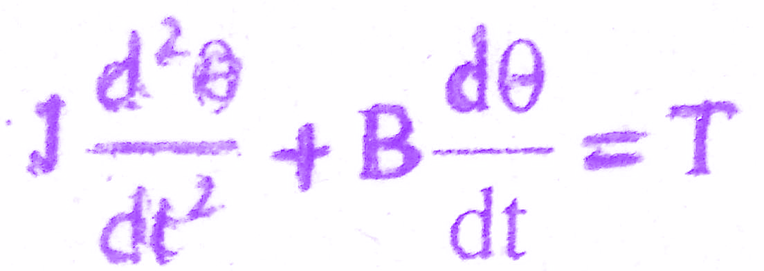
The mechanical system of the motor is shown in the below figure.

The differential equation governing the mechanical system of motor is given by
The back emf of DC machine is proportional to speed (angular velocity) of shaft.
Must Read:
The Laplace transform of various time domain signals involved in this system are shown below.
L{va} = Va(s); L{eb} = Eb(s) ; L{T}= T(s) ; L{ia} = la (s) ; L{θ} = θ(s)
The differential equations governing the armature controlled DC motor speed control system are
On taking Laplace transform of the above equations with zero initial conditions we get,
Ia(s) Ra + La sIa(s) + Eb(s) = Va(s) => (1)
T(s) = Kt Ia(s) => (2)
J s θ(s) + B s θ(s) = T(s) => (3)
Eb(s) = Kb s θ(s) => (4)
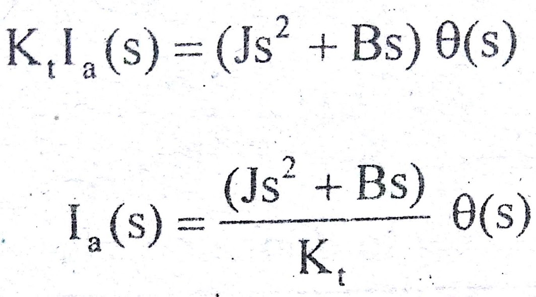
On equating the above equations (2),(3) we get
Equation (1) can be written as,
(Ra + sLa) Ia(s) + Eb(s) = Va(s) => (6)
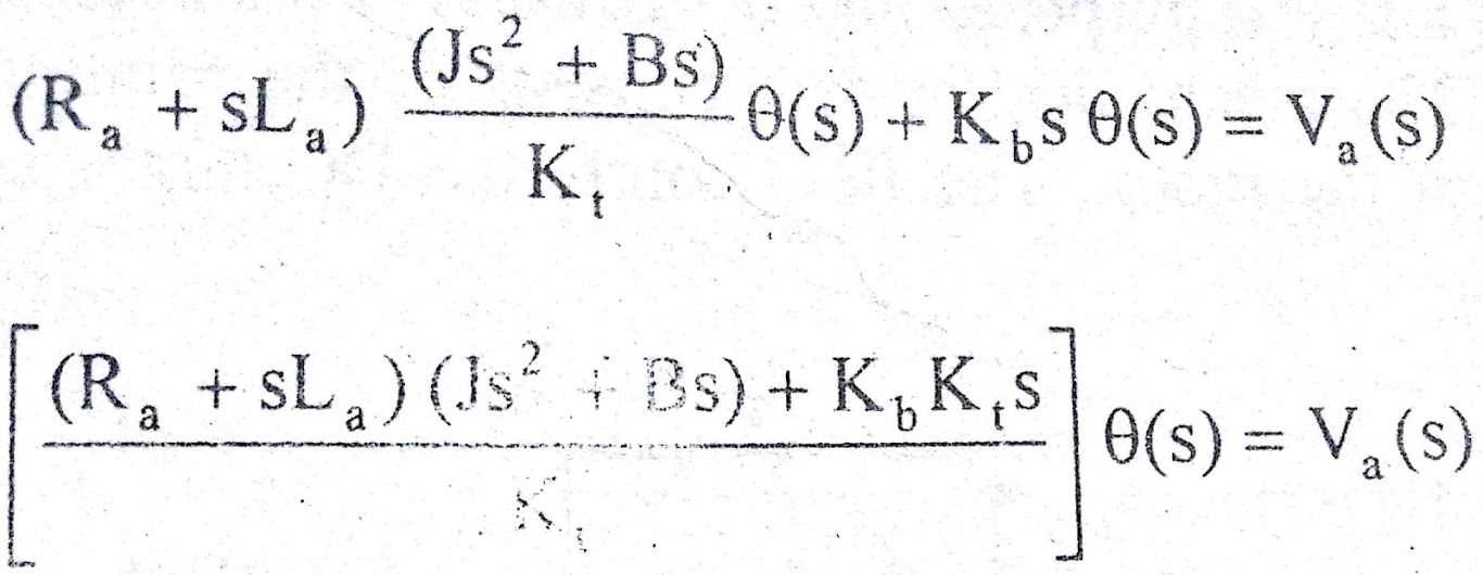
Substituting for Eb(s) & Ia(s) from (4),(5) respectively in equation (6)
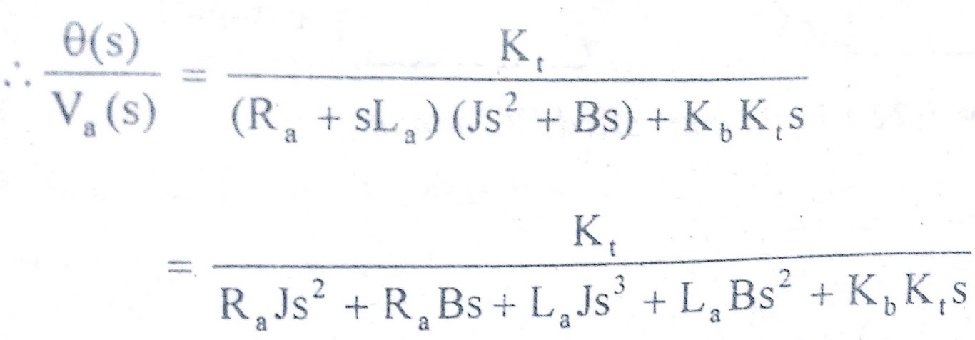
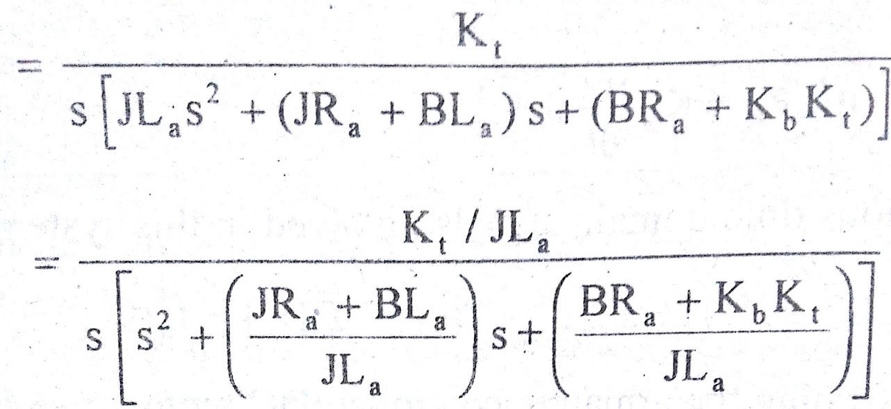
The required transfer function of armature controlled dc motor is θ(s)/Va(s)
Must Read:

The transfer function of armature controlled dc motor can be expressed in another standard form as shown below. From the equation (7) we get,
where La/Ra = T = Electrical time constant
J/B = Tm = Mechanical time constant
Conclusion:
In this post we have learnt about, transfer function of armature controlled DC motor. You can download this article as pdf, ppt.
Comment below if you have something to say!
