Measurement of Capacitance By DeSauty’s Bridge:
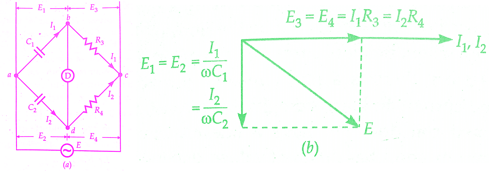
DeSauty’s Bridge is the simplest method of comparing two capacitances. The connections and the phasor diagram of DeSauty’s Bridge are shown in the below figure.
Let C1 = capacitor whose capacitance is to be measured,
C2 = a standard capacitor, and
R3, R4 = non-inductive resistors.
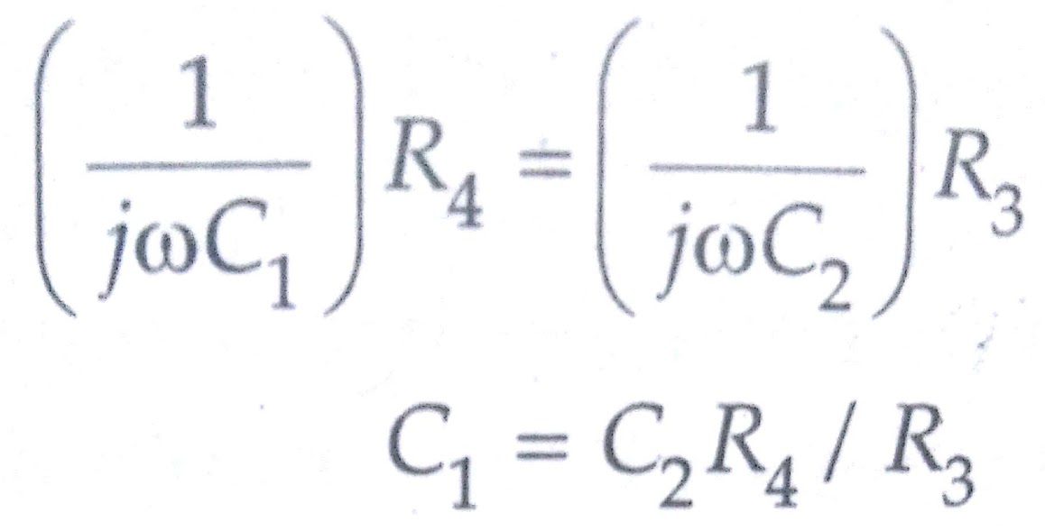
At balance,
The balance can be obtained by varying either R3 or R4. The advantage of DeSauty’s Bridge is its simplicity. But this advantage is nullified by the fact that it is impossible to obtain balance if both the capacitors are not free from dielectric loss. Thus with DeSauty’s Bridge, only loss-less capacitors like air capacitors can be compared.
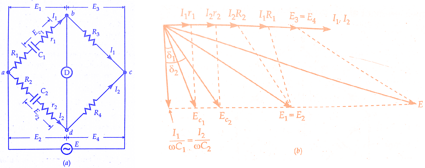
In order to make measurements on imperfect capacitors (i.e., capacitors having a dielectric loss), DeSauty’s Bridge is modified as shown in the below figure. This modification is due to Grover.
Resistors R1 and R2 are connected in series with C1 and C2 respectively. r1 and r2 are resistances representing the loss component of the two capacitors.
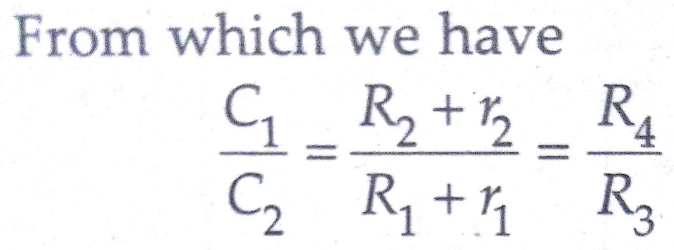
At balance,
The balance may be obtained by variation of resistances R1, R2, R3, R4. The above figure (b) shows the phasor diagram of the DeSauty’s Bridge under balance conditions. The angles δ1 and δ2 are the phase angles of capacitors C1 and C2 respectively.
Also Read:
Dissipation factors for the capacitors are :
D1 = tan δ1 = ωC1r1 and
D2 = tan δ2 = ωC2r2
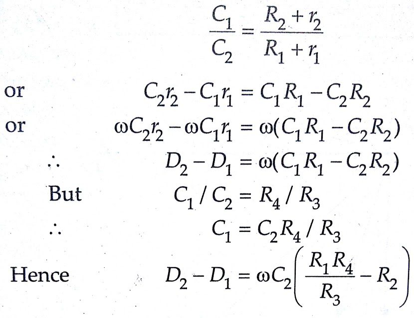
From the above equation, we have
Therefore, if the dissipation factor of one of the capacitors is known, the dissipation factor for the other can be determined.De Sauty’s Bridge does not give accurate results for dissipation factor since its value depends on the difference of quantities R1R4/R3 and R2.
These quantities are moderately large and their difference is very small and since this difference cannot be known with a high degree accuracy, the dissipation factor cannot be determined accurately.
Conclusion:
In this, we have learnt the measurement of Capacitance By De Sauty’s Bridge. You can download this article as pdf, ppt.
Comment below if you have any queries!
Sir what are the applicatios of de-satuys bridge
Thank you for your comment and for asking about the applications of a De-Sauty’s bridge. A De-Sauty’s bridge is a type of electrical measuring instrument that is used to measure the unknown inductance of a circuit. It is commonly used in electrical engineering and physics labs to experimentally determine the inductance of various types of circuits. The De-Sauty’s bridge is particularly useful for measuring the inductance of high-frequency circuits, as it is more accurate than other methods at these frequencies. I hope this helps to answer your question! If you have any further questions or comments, please don’t hesitate to ask.