A transfer function is a mathematical representation that characterizes the relationship between the input and output of a dynamic system. In the case of field-controlled DC motors, the transfer function describes the relationship between the armature voltage and the angular speed (or rotational speed) of the motor shaft. This relationship is pivotal for designing controllers and predicting motor performance under different conditions.
Components of the Transfer Function:
The transfer function of a field-controlled DC motor consists of several elements that together define its behavior:
Armature Circuit Dynamics: The armature circuit includes the armature winding and a connected resistor. The voltage applied to the armature determines the electromagnetic torque produced. The transfer function accounts for the dynamics of the armature circuit, translating voltage changes into current variations and ultimately affecting the motor’s speed response.
Field Circuit Dynamics: The field circuit, comprising the field winding and a field resistor, controls the strength of the magnetic field in the motor. The field current influences the motor’s torque production capability. The transfer function captures the interplay between the field current and the motor’s angular speed, shedding light on the motor’s overall performance.
Mechanical Dynamics: The mechanical components of the motor, such as the rotor’s inertia and damping factors, introduce inertia and friction effects that impact the motor’s acceleration and deceleration. These mechanical dynamics are crucial in understanding the motor’s transient response to changes in input voltage.
Significance of Transfer Function Analysis:
Analyzing the transfer function of a field-controlled DC motor offers several key advantages:
Controller Design: Engineers use the transfer function to design appropriate control strategies for achieving desired motor responses. By manipulating the transfer function, they can design feedback control loops that regulate the motor’s speed, position, or torque with precision.
System Performance Prediction: The transfer function helps in predicting the motor’s behavior under different operating conditions. Engineers can simulate various scenarios and anticipate how the motor will respond to changes in input voltages, load variations, or disturbances.
Stability Analysis: Stability is a critical aspect of control system design. The transfer function aids in analyzing the stability of the closed-loop control system. It enables engineers to determine the system’s stability margins and tune controller parameters for optimal performance.
Dynamic Response: Understanding the transfer function provides insights into the dynamic response of the motor. Engineers can analyze parameters such as rise time, settling time, and overshoot, which are crucial in assessing the motor’s performance in real-time applications.
Real-World Applications:
The transfer function of field-controlled DC motors finds application in various industries:
Industrial Automation: Field-controlled DC motors are widely used in conveyor systems, material handling, and robotic applications. Analyzing the transfer function allows engineers to optimize these systems for efficiency and accuracy.
Machine Tools: Transfer function analysis helps design precision machine tools where controlled motor movement is essential for achieving accurate machining operations.
Textile Industry: In the textile industry, field-controlled DC motors are employed in yarn winding and weaving machines. Understanding the transfer function aids in achieving consistent thread tension and improving product quality.
Process Control: Transfer function analysis plays a pivotal role in process control systems, such as those used in chemical processing plants or temperature control systems.

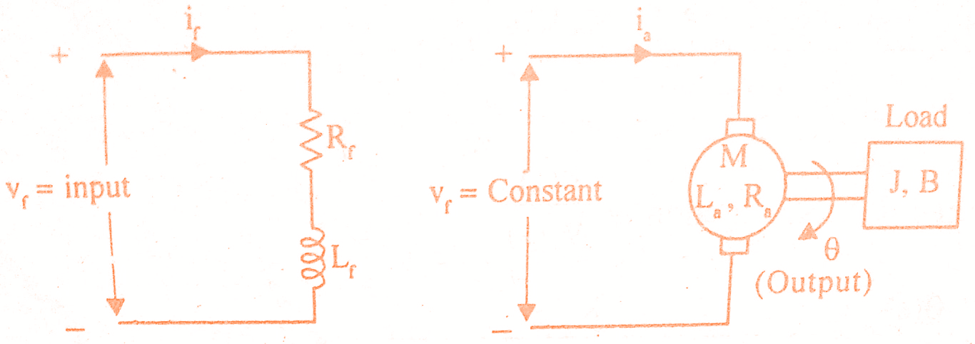
The speed of a DC motor is directly proportional to armature voltage and inversely proportional to flux. In field controlled DC motor the armature voltage is kept constant and the speed is varied by varying the flux of the machine. Since flux is directly proportional to field current, the flux is varied by varying field current. Here we will learn derivation of transfer function of field controlled dc motor.
The speed control system is an electro-mechanical control system. The electrical system consists of armature and field circuit but for analysis purpose, only field circuit is considered because the armature is excited by a constant voltage. The mechanical system consists of the rotating part of the motor and the load connected to the shaft of the motor. The field controlled DC motor speed control system is shown in the below figure. For this field controlled DC motor we shall find transfer function.
Let Rf = Field resistance
Lf = Field inductance
if = Field current
Vf= Field voltage
T = Torque developed by motor
Kt = Torque constant
J = Moment of inertia of rotor and load
B = Frictional coefficient of rotor and load
Must Read:
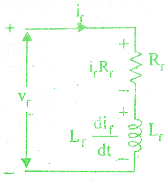
The equivalent circuit of field is shown in the below figure.
By Kirchoff ‘s voltage law, we can write

The torque of DC motor is proportional to product of flux and armature current. Since armature current is constant in this system, the torque is proportional to flux alone, but flux is proportional to field current.
T ∝ ir
Torque , T = Ktf ir
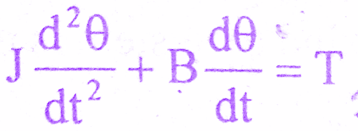
The mechanical system of the motor is shown in the below figure.

The differential equation governing the mechanical system of the motor is given by,
The Laplace transform of various time domain signals involved in this system are shown below.
L{if} = If(s) ; L{T} = T(s) ; L{vf} = Vf(s) ; L{θ} = θ(s)
The differential equations governing the field controlled DC motor are,in the derivation of transfer function of field controlled dc motor.

Must Read:

On taking Laplace transform of the above equations with zero initial condition we get,
Rf If(s) + Lf s If(s) = Vf(s) => (1)
T(s) = Ktf If(s) => (2)
J s² θ(s) + B s (s) = T(s) => (3)
Equating equations (2) & (3) we get,
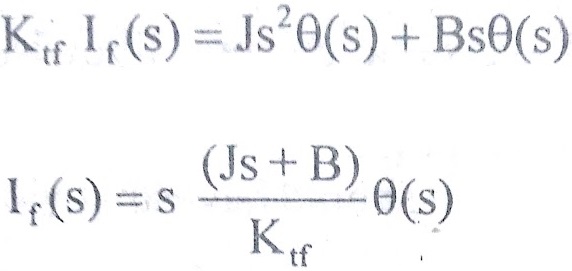
=> (4)
The equation (1) can be written as
(Rf + sLf) If(s) = Vf(s) => (5)
Must Read:
On substituting to If(s) from equation (4) in equation (5) we get,transfer function of field controlled dc motor.
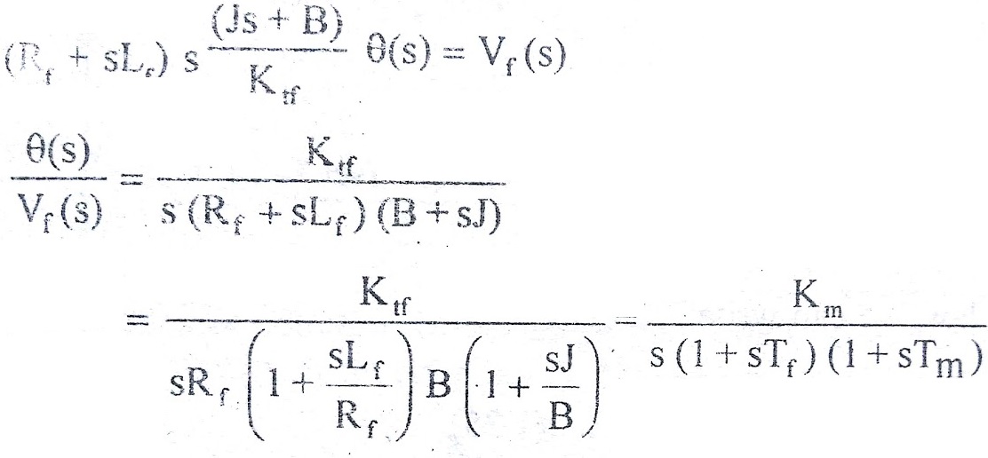
where Km = Ktf/Rf B = Motor gain constant
Tf = Lf/Rf = Field time constant
Tm = J/B = Mechanical time constant
Conclusion:
In the realm of industrial automation, the transfer function of field-controlled DC motors stands as a critical tool for engineers and designers. Its ability to capture the intricate relationship between input voltage and motor speed empowers them to optimize motor performance, design efficient control systems, and ensure stability and reliability in diverse applications. By delving into the components, significance, and real-world applications of the transfer function, we gain a deeper appreciation for the role these motors play in driving technological advancements across industries.
In this post we have learnt Transfer Function of Field Controlled DC Motor. You can download this article as pdf, ppt.
Comment below if you have any queries!
